Version v1.3.0 of the documentation is no longer actively maintained. The site that you are currently viewing is an archived snapshot. For up-to-date documentation, see the latest version.
Configuring GPIO Inputs
Overview
OpenMower supports configuring GPIO pins as digital inputs that can trigger emergency stops or other events. Common use cases include:
- Wheel lift sensors — detect when the mower is lifted
- Stop buttons — physical emergency stop buttons on top of the mower
- Collision sensors — detect when the mower hits an obstacle
Step 1: Create the inputs configuration file
Instead of writing your inputs.yaml from scratch, we recommend starting from a ready-made hardware-specific configuration and adjusting it to your wiring. You can find pre-built configs for your Carrierboard at:
https://github.com/ClemensElflein/open_mower_ros/tree/main/src/open_mower/params/hardware_specific
Download the appropriate inputs.yaml and place it at /home/openmower/params/inputs.yaml.
Here is a minimal example for reference:
gpio:
  - name: Front left wheel lift
    line: GPIO10
    active: low
    emergency:
      reason: lift
      delay: 2500

  - name: Front right wheel lift
    line: GPIO11
    active: low
    emergency:
      reason: lift
      delay: 2500

  - name: Top stop button 1
    line: GPIO12
    active: low
    emergency:
      reason: stop
      delay: 10

  - name: Top stop button 2
    line: GPIO13
    active: low
    emergency:
      reason: stop
      delay: 10
Configuration fields
| Field | Description |
|---|---|
name | Human-readable label for the input |
line | GPIO pin name (e.g. GPIO10) |
active | Logic level that triggers the event — low or high |
emergency.reason | Emergency type — lift for wheel lift, stop for stop button, collision for obstacle detection |
emergency.delay | Debounce/delay in milliseconds before the emergency is triggered |
GPIO Pin Mapping
The example config above uses GPIO10–GPIO13. Here is how those map to physical connectors on each board.
OpenMower Yardforce Board as of v1.2.0
As of this Yardforce Board version, you may choose between the previous OM JST-XH connectors, which mainly exist for HWv1 upgraders, or the OEM cabling via the CoverUI, which is targeted at new installations.
For this selection to work properly, the board has a Hall-Multiplexer (MUX) which is configured in inputs.yaml as follows:
yf_cover_ui:
  # ---- Hall Inputs Source Selector ----
  # "om" when the hall sensors get connected to the XHST plugs of the OpenMower board
  #      (or the robot-adapter-pinheader)
  # "oem_idc" when the hall sensors get connected to the (non-modded) OEM CoverUI board
  #      (and CoverUI get connected via the 16pin IDC cable to the OpenMower board)
  - name: Hall Inputs Source Selector
    id: hall_mux
    value: oem_idc
Depending on how you switch the Hall-MUX, the GPIOs are mapped as shown in this image:
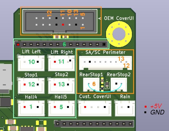
The green-highlighted plugs/GPIOs are those for Hall-MUX om, whereas the orange-highlighted plugs are the ones for Hall-MUX oem_idc.
OpenMower Yardforce Board up to v.1.1.0-beta
Orientation: looking at the board with the ethernet ports at the bottom left, pins sorted top to bottom.
| Position | GPIO |
|---|---|
| 1st (topmost) | GPIO10 |
| 2nd | GPIO11 |
| 3rd | GPIO12 |
| 4th | GPIO13 |
OpenMower Universal Board
Orientation: looking at the board with the ethernet ports facing you.
| Position | GPIO |
|---|---|
| Top left | GPIO13 |
| Top right | GPIO12 |
| Bottom right | GPIO11 |
| Bottom left | GPIO10 |
OpenMower SABO / John Deere Board
For changes to the default inputs config of the SABO / John Deere Carrierboard, we recommend downloading the default inputs.yaml
Step 2: Enable the input service
Add the following to your mower_params.yaml (or custom_params.yaml for Universal board builds):
ll:
  services:
    input:
      config_file: /data/params/inputs.yaml
To open the file for editing:
openmower configure ros
Path mapping on OSv2
On OSv2,/home/openmower/params is mapped to /data/params inside the container. If you are on a different setup, adjust the config_file path accordingly.Step 3: Restart OpenMower
After saving both files, restart the service to apply the changes:
openmower restart
Your GPIO inputs are now active and will trigger the configured emergency events when the specified logic level is detected.