Assembling the YardForce Classic 500
Assembling the robot with Vermut’s 0.13.x kit.
Connect bottom wires
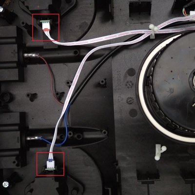 1 Plug in wheel hall sensor wires
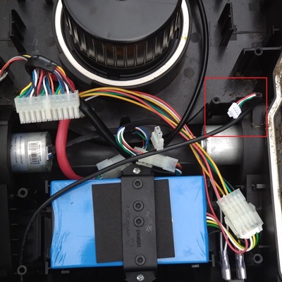 2 Find external USB socket cable
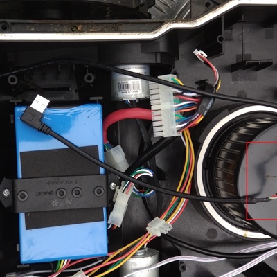 3 Connect RPi USB adapter
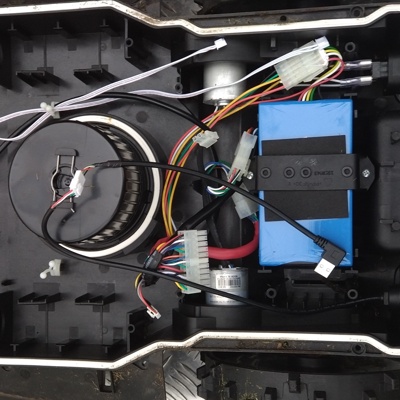 4 Well done!
Install GPS antenna
The second picture is not perfect, the screw is out of the frame, yellow arrow pointing at it. Also, the GPS plane itself is historic from 0.9.3, yours will be green and shiny.
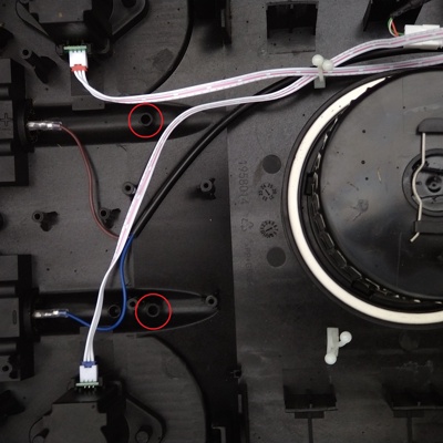 1 Organize the cables, free the mounting holes, unscrew central screw
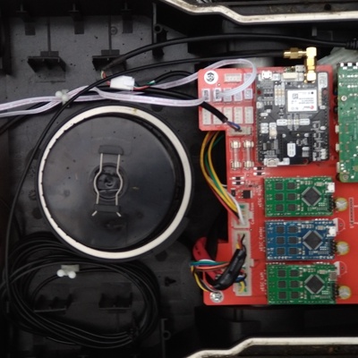 2 Install the GPS antenna assembly, screw the central screw
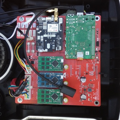 3 Organize excess cable, connect it to GPS board
Install external Wi-Fi adapter (optional)
🔧
This is optional and will vary with the size and shape of your adapter, because right now there is no “official” external adapter and people are installing all kinds of stuff. Depicted isAlfa USB Adapter AWUS036NHV, on the
rtl8188eu chip using custom driver.⚠️
Important: If you install an external WiFi USB adapter, it might prevent you from seeing the OpenMower hotspot during initial setup. For first startup, it’s recommended to keep the external adapter disconnected until you’ve completed the initial WiFi configuration. After successfully connecting to your network, you can then connect the external adapter.Assemble mainboard
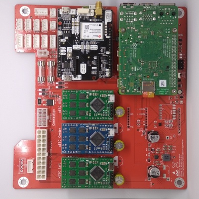
This step assumes that you did all previous configuration steps from the documentation.
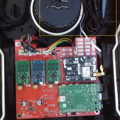
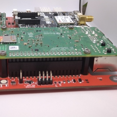
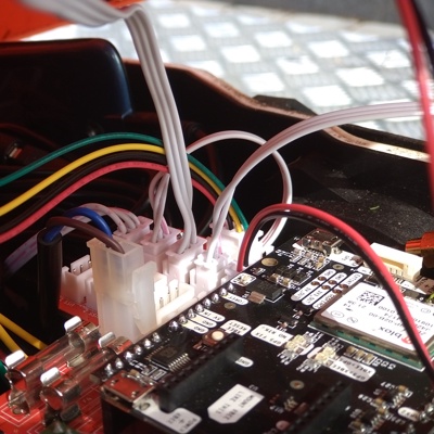
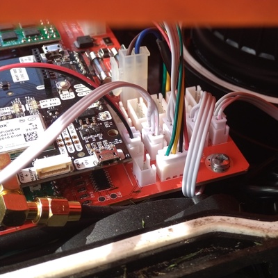
Connect and screw mainboard
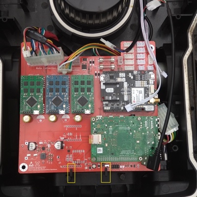 1 Put the board in place, make sure bottom holders are in
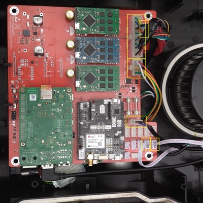 2 Connect the cables
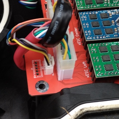 3 Close-up of motor sensor cable
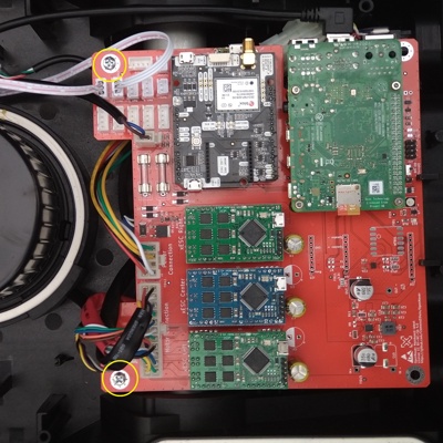 4 Fasten the board with 2 screws in top
Modify rain sensor cable (kit version specific)
🔧
Kits till mid-2023 included incorrect rain sensor cable that has female connectors on both sides. This is a hacky example of how this can be fixed. Alternatively, you can cut them and just solder together.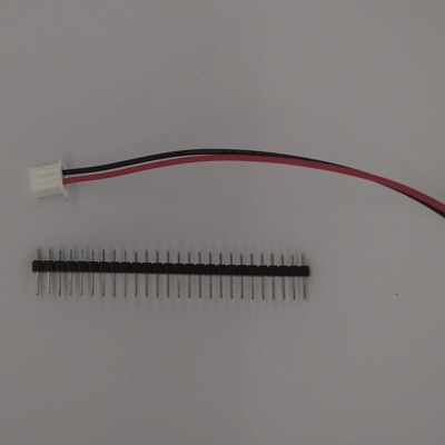 1 Take pin header
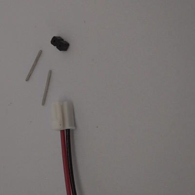 2 Pry 2 pins from harness
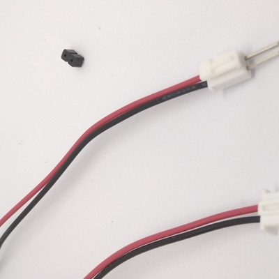 3 Insert them to smaller connector
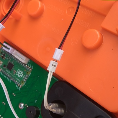 4 Plug it to rain sensor connector either side
Assemble cover
🔧
This section assumes that you are completely replacing the stock UI board with custom one. There is an experimental option to reuse stock board with custom firmware. If you are going to go this path - everything that is cover-related would be different for you. You can find more information in Discord, as of now it’s work in progress.On the photos you see an old patched version of rain sensor cable (see above). Yours might just fit in normally.
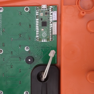 1 Carefully align button and leds with holes, screw the board
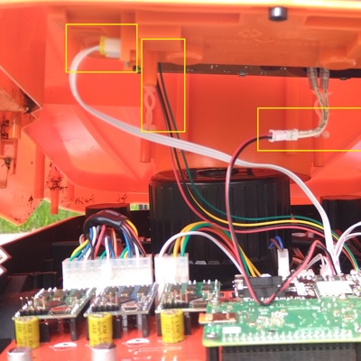
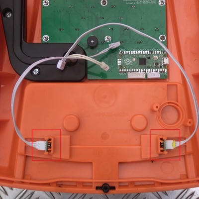 2 Connect stop button hall sensor wires
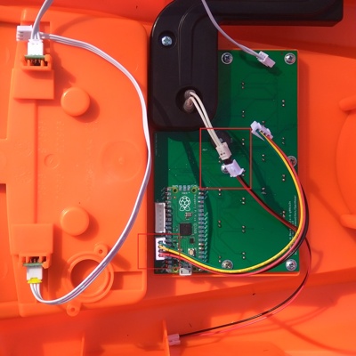 3 Connect UI wire and rain sensor wire
Connect cover to bottom
Close the cover
Alight cutting height knob with mower motor, close the cover, push where needed to snap the latches. Or even leave it lying on while you testing the setup, maybe you’ll need to open it again.
Last modified April 22, 2025: Add warning about external WiFi adapters affecting initial setup (3941304)
