Step 2.1: Prepare the GPS
Update Firmware and configure the GPS board
Info
There is a tutorial video available for this step of the process!
Check my YouTube video here: Video
(time 16:21 - 17:15)
Prerequisites
- An Ardusimple F9P GPS board
- A Micro USB Cable
- A Windows PC
- Latest v1 version of the u-center software:
🔗 https://www.u-blox.com/en/product/u-center
Don’t get u-center V2, you will need u-center v1 for the F9P. - The GPS configuration file
🔗 robot-fw-1_51.txt
This will open in a new browser tab. Use Ctrl+S to download the file.
Step 2.1.0: Update Firmware
Warning
The F9P now exists in multiple variants. The firmware below is for the L1 + L2 version. Make sure that on the u-blox chip, it says one of the following: ZED-F9P-02B, ZED-F9P-04B or ZED-F9P-05B!.
If it’s a different board, don’t use the linked firmware, get it from u-blox.com directly.
Update the firmware of your Ardusimple board to version ZED-F9P HPG 1.51 - link here
. There’s a guide on the Ardusimple Website
.
Step 2.1.1: Open u-center and connect to your GPS
After installing u-center, connect your Ardusimple board using the “Power+GPS” USB socket to your Windows computer. You should see the blue LEDs of the board come on and Windows should recognize the device as a COM port. With the module connected to your PC, open the u-center software.
In u-center, first connect to your board by selecting the appropriate COM port in the Receiver -> Connection menu.
Step 2.1.2: Transfer the configuration to the GPS
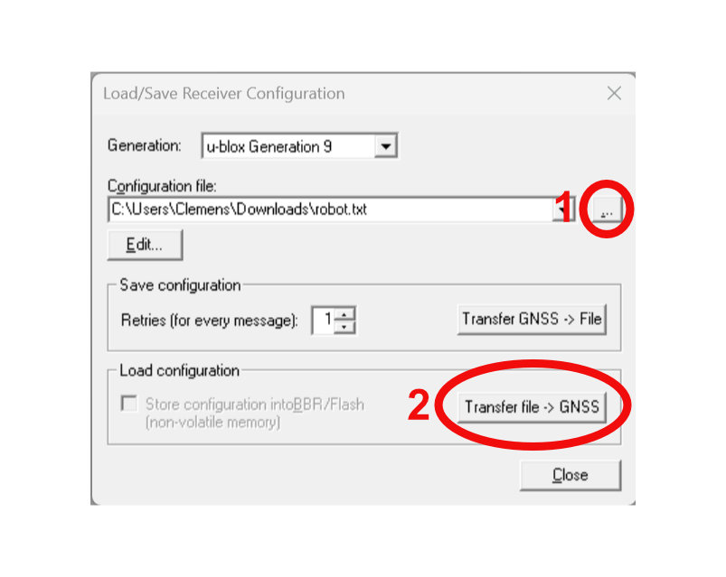
After successfully connecting to the board, you can transfer
the previously downloaded configuration file robot-fw-1_51.txt by opening the window Tools -> Receiver Configuration .... In this window you open the robot-fw-1_51.txt using the ... button and then transfer the configuration to the GPS by clicking the Transfer File -> GNSS button.
Step 2.1.3: Save configuration to Flash
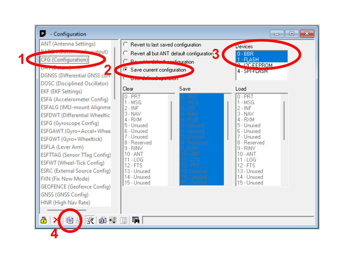
In order to keep the GPS configured even after powering it down, you need to save the current configuration to Flash memory. In order to do this, select View -> Configuration View. In the new window you need to select CFG (Configuration) in the list on the left side and then enable Save current configuration. Make sure that 0 - BBR and 1 - FLASH are both selected on the right side of the window. Once that’s done, click the Send button in the lower toolbar of the window.
Once successful, there will be a timer showing on the upper right side of the window. This is the timer since the last message was sent to your GPS board. It should be 0s directly after clicking Send.
Step 2.1.4: Done 🎉
Your GPS is now configured for use with the Open Mower software. You can disconnect it from your Windows PC.
Connect your UM9xx to your PC using the supplied USB-C cable
Open a serial terminal (minicom, miniterm, CuteCom, etc.) at 115200 baud
Take attention that your line-end termination has to be CR/LF
Send
CONFIG↵ Enter to verify the connection. You should see readable key/value style output. If not, check cable, port, and permissions.Reset and switch the baud rate to 921600 by entering the following commands, line by line:
FRESET↵ Enter
CONFIG COM1 921600↵ Enter(After
FRESETthe module may take a few seconds to respond.)Re-check connection with the simple
CONFIGcommand. If you don’t get similar results than before, change your serial terminal speed to 921600 baud (re-open if necessary) and runCONFIGagain, till your get a reasonable responseApply the rover configuration by entering the following commands, line by line:
MODE ROVER UAV↵ Enter
GPGSV COM1 2↵ Enter
GPRMC COM1 1↵ Enter
GPGSA COM1 1↵ Enter
GPVTG COM1 1↵ Enter
GPGST COM1 1↵ Enter
GPGGA COM1 0.2↵ Enter
SAVECONFIG↵ EnterTake attention to the
SAVECONFIGcommand, which stores settings so they survive power cycles.Unplug the USB cable from the UM9x module and mount it to the CarrierBoard (solder required headers first if required).
Using USB (cutecom)
For using it with the M20, replace every COM1 with COM2.
Connect your M10 to your PC using the supplied USB-C cable.
Open the recommended terminal program, cutecom.
Connect at 115200 baud.
You should see readable key/value style output. If not, check cable, port, and permissions.
Make sure your line-end termination is set to CR/LF.
In cutecom, you may switch off the output — it keeps running but won’t be displayed.
Factory reset and disable cyclic outputs by entering the following commands, line by line:
FRESET↵ Enter
(AfterFRESETthe module may take a few seconds to respond.)UNLOGALL↵ Enter
Switch the output back on in cutecom.
Re-check the connection with the simple command:
LOG VERSION ONCE↵ Enter
You should see readable output.
Apply the rover configuration:
SERIALCONFIG COM1 460800↵ Enter
Re-check the connection using:
LOG VERSION ONCE↵ Enter
You should still see readable output because we are connected on COM3. If not, check the connection and baud rate.
Continue with the rover configuration:
LOG COMCONFIG ONCE↵ Enter
(COM1 should show 460800 now)
RTKTYPE ROVER↵ Enter
RTKTYPE↵ Enter
RTKTIMEOUT 5↵ Enter
RTKTIMEOUT↵ EnterDefine the cyclic output:
LOG COM1 GPGSV ONTIME 1↵ Enter
LOG COM1 GPRMC ONTIME 1↵ Enter
LOG COM1 GPGSA ONTIME 1↵ Enter
LOG COM1 GPVTG ONTIME 1↵ Enter
LOG COM1 GPGST ONTIME 1↵ Enter
LOG COM1 GPGGA ONTIME 0.1↵ EnterFinally, save the changes to flash memory:
SAVECONFIG↵ Enter
Pay attention to the
SAVECONFIGcommand — it stores settings so they survive power cycles.Unplug the USB cable from the M10 module and mount it to the CarrierBoard (solder headers first if needed).
Remember to adapt the baud rate in the OpenMower ROS configuration:
gps:
  baud_rate: 460800
  protocol: "NMEA"
Using TCP (by_connect)
This section works on Linux and Windows (on Linux, run by_connect under Wine). You need to postpone this step until your OpenMower system is running. The configuration is done remotely over TCP.
Prerequisites
- A WitMotion ByNav M10 GPS board (default baud rate: 115200)
- An OpenMower with OpenMowerOS installed
- A Windows or Linux PC
- by_connect software from bynav.com
- Interface protocol description (PDF) — valid for all ByNav modules (M10, M20, etc.)
For using it with the M20, replace every COM1 with COM2.
- Mount the M10 to the CarrierBoard (solder headers first if needed).
- Set the baud rate in the OpenMower ROS configuration to 115200:
gps:
  baud_rate: 115200
  protocol: "NMEA"
Connect your M10 via TCP-serial by running
openmower expose-gpsfrom your OpenMower SSH terminal: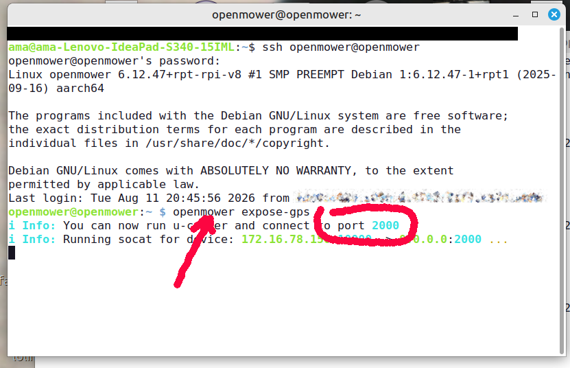
Open by_connect on your PC (download from bynav.com; on Linux, start it with Wine) — connect as TCP Client to OpenMower port 2000 (no baud rate needed):
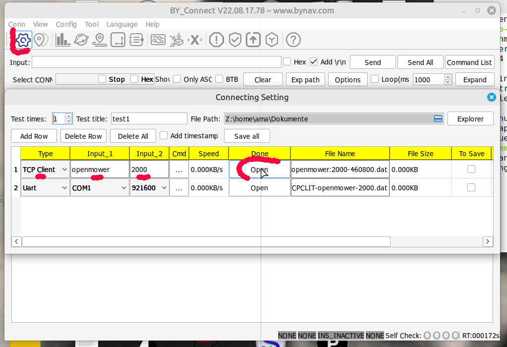
You should see readable key/value style output. If not, check the connection.
Make sure your line-end termination is set to CR/LF.
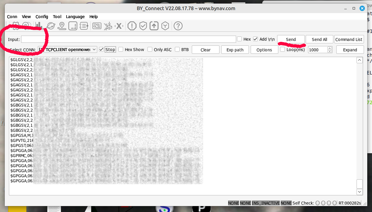
In by_connect, you may switch off the output — it keeps running but won’t be displayed:
Factory reset and disable cyclic outputs by entering the following commands, line by line:
FRESET↵ Enter
(AfterFRESETthe module may take a few seconds to respond.)UNLOGALL↵ Enter
Switch the output back on in by_connect.
Re-check the connection with:
LOG VERSION ONCE↵ Enter
You should see readable output.
Apply the rover configuration:
SERIALCONFIG COM1 460800↵ Enter
Re-check the connection:
LOG VERSION ONCE↵ Enter
The output will be unreadable now because the baud rate has changed. Close the connection, update the baud rate to 460800 in the OpenMower ROS configuration, and reconnect via
openmower expose-gps: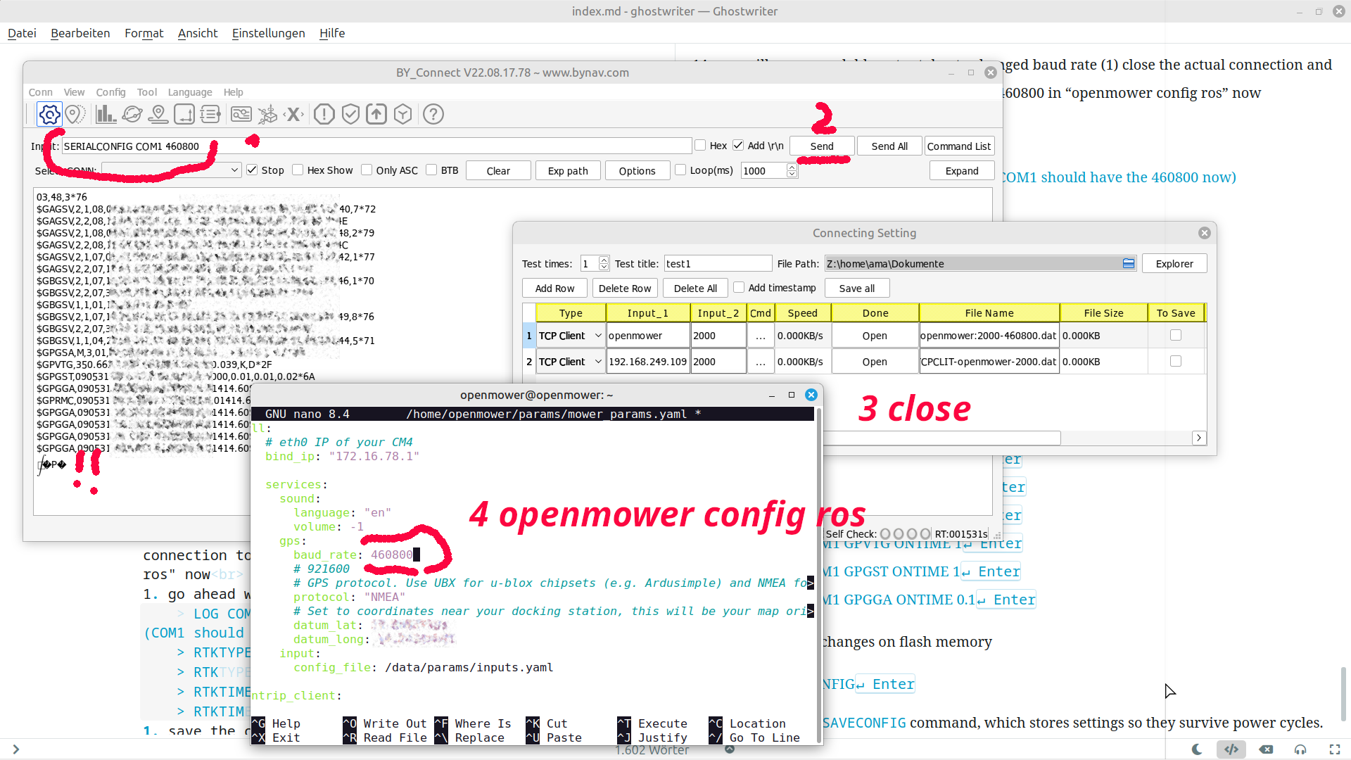
Reopen by_connect, connect as TCP Client again, and verify readable output with:
LOG COMCONFIG ONCE↵ Enter
Continue with the rover configuration:
RTKTYPE ROVER↵ Enter
RTKTIMEOUT 5↵ EnterIf all worked as expected (you receive
okresponses), save the settings to flash memory — otherwise disconnect, power cycle the OpenMower, and start over:SAVECONFIG↵ Enter
Define the cyclic output:
LOG COM1 GPGSV ONTIME 1↵ Enter
LOG COM1 GPRMC ONTIME 1↵ Enter
LOG COM1 GPGSA ONTIME 1↵ Enter
LOG COM1 GPVTG ONTIME 1↵ Enter
LOG COM1 GPGST ONTIME 1↵ Enter
LOG COM1 GPGGA ONTIME 0.1↵ EnterSave the changes to flash memory:
SAVECONFIG↵ Enter
Pay attention to the SAVECONFIG command — it stores settings so they survive power cycles.
Continue with Step 2.2: Prepare the SD Card